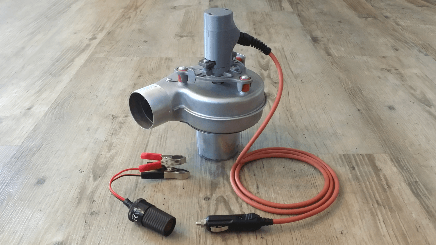
The engineer’s little helper to get things started.
Starting out this hobby nearly from scratch, a steam raising blower was needed for the Feldbahn 0-6-0. As of so often there are many offers to be found on the internet – and just as reliable, either they don’t fit the engine or the engineer’s purse. And so it starts – an own 12V DC steam raising blower project.
BTW, this blower should also fit a Stafford or General Gordon.
Trivia
From what I’ve seen so far, there are two common designs which serve the purpose to raise steam after the fire is first lit:
- A rotating, electrically driven impeller (put on the chimney) that generates a radial airflow, resulting in a negative pressure, which in turn generates the needed draught in the firebox. Either with guided or unguided exhausts.
- A J-shaped pipe which is lowered down the chimney and connected to pressured air, functioning like the locomotive’s own blower.
With the thought in mind that a 12V battery can easily be carried around, and will be available in most situations (a source for pressured air might not) I went for an electric driven, radial blower with guided exhausts. So I will be able to start the engine either at my property or elsewhere.
During my previous researches for a purchasable blower, I stumbled across one that was rated for 230V AC. I liked the general design, but that thing would have sucked not only the exhausts, but most likely the entire firebox’s content up the chimney. So this was rather ’not ideal’ and adjustments had to be made.
Ordering Parts
As it was in the ‘affordable’ range (about 30 bucks under a kit), there was still some room for a suitable motor that was rated 12V DC, so I ordered it. Ok, to be fair, this was the calculation I served my wife at the dinner table, but you know the reality as well as I do… The blower came with no information about RPMs or even capacity (and even if, I replaced the original motor), so I had to figure out the sweet spot myself. As I was not highly interested in playing around with 230 volts, I also ordered a random low power 12V DC motor, somewhere in the range up to 10,000 RPM that could be easily regulated with my laboratory power supply. Of course, I don’t need a motor with such a specification for this project, but this motor was not meant to stay on the blower anyway.
Figuring Out the Right RPM
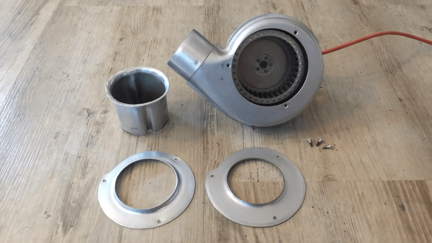
When both components arrived (blower and low power motor) I dismantled the blower to get rid of the 230V motor, and deburred the dangerously sharp edges, left by the manufacturer. Then I took some 8 mm round stock to make an adapter, connecting the 12V motor with the impeller. After this contraption did show enough stability, I was interested in the general performance of my setup. So a piece of firestarter was lit in the firebox, and the blower was put onto the chimney. I fiddled around for a while, but was never really satisfied with the results, because I was not able to get any information out of this setup to specify a suitable 12V DC motor with the right RPMs. So I bought a speedometer, and gave the experiment another try. This time not only with a bit of firestarter, no, I went ‘all in’ and steamed up the loco completely. While I regulated the voltage (and thus the draught) with my laboratory power supply, I took notes from the different voltage values, I experimented with, to measure the RPMs afterwards when I got better access to the spinning parts. It turned out that something between 1,500 and 2,000 RPM would generate the right amount of draught to bring the boiler to 70 PSI in about 45 to 60 minutes.
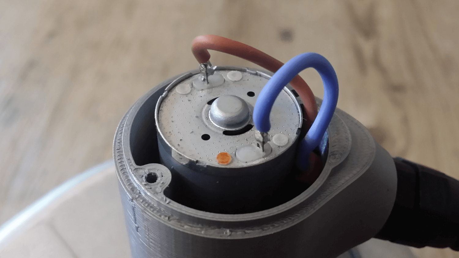
So I ended up using a gearbox 12V DC motor with 1,700 RPM (idle), which would be something around 1,500 RPM under working conditions. Another live test proved this setup as functioning.
Motor Mount
The motor is mounted on a simple, custom-made steel bar, which itself is screwed to the original motors’ aluminium cast (the triangular shaped thing on top of the blower), using the already existing threaded metric holes.
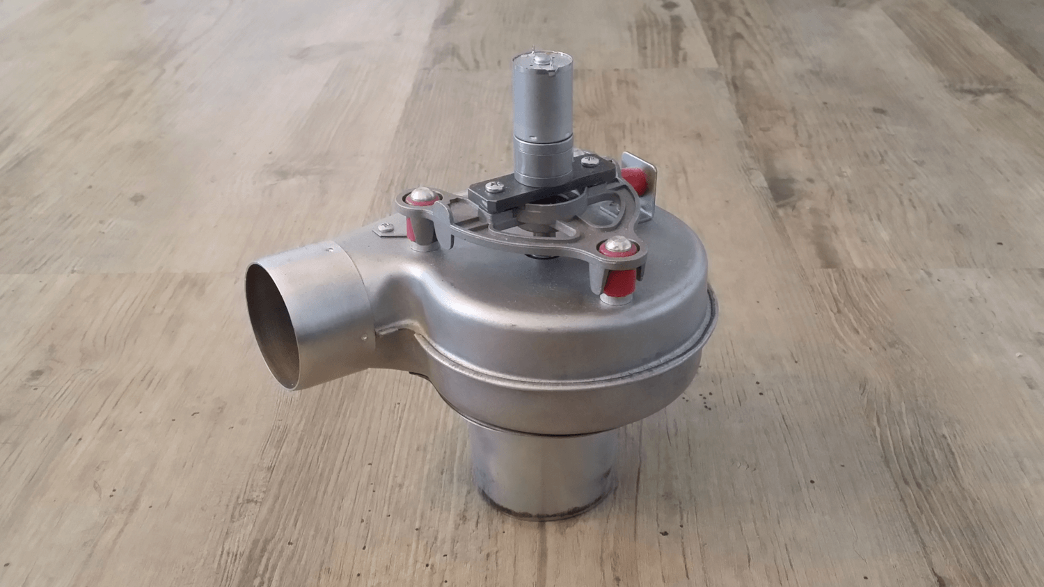
Motor Case
At this point in time I’m putting a PLA-print to the test. I’m not too optimistic with that in terms of temperature resilience, since it is made of a material that is meant to melt at comparably low temperatures. But it was the fastest way to get a (at least visually) functional motor case.
The case is basically clamped in place by the bar the motor is mount on, and the round casting, where the lower old motor bearing was fit into.
The strain relief (stock item), screwed into the side of the motor case, brings the cable further away from the eventually hot blower. Also, it serves the obvious function to prevent the cable from pulled out of the motor casing or being kinked right at the inlet.
Funnel
The stock blower came without a specific mount for a steam engine chimney, so one had to be built.
I thought, the easiest way would be to take some tin rainwater pipe, and somehow mount it on the bottom part of the blower. This general idea was put into action, but I had to make some crucial adjustments. First I couldn’t find a pipe that matches both openings, the chimney’s and the blower’s. So I ended up using an 80 mm one. I bent the upper edge outwards, so it could be clamped between two rings. One of these rings was cut out of the original mounting plate (see fig. 2, right ring). The other was made from an 80 mm tin cover rosette, from which I cut off the collar.
To make the funnel fit into the chimney, it had to be decreased in diameter at the other end. I did that by simply making two rather large inward dents with a pair of round nose pliers. After this adjustment the funnel snugs into the chimney with about 20 mm inset – plenty enough to keep it up there solidly. I might lose some efficiency there, because some air can easily bypass the firebox now – but as written before, firing up was no problem with this setup.
The funnel design also comes with an unintentional bonus: The exhaust outlet can be rotated freely while the blower sits solidly on the chimney, as the funnel isn’t rigidly connected to the blower.
Cabling
To bring power from the source to the motor, I took a 1.5 m silicon cable and fitted a 12V cigarette plug at its end. The idea was to use a plug within the common automotive 12V DC system. This standard, however, wouldn’t help when I take a battery as a power source. So I also ordered an adapter with two battery clamps. The other end is soldered to the motors pins.
Design Flaws
Sooner or later I will have to replace the standard steel screws with some stainless ones, as these exhausts are working pretty hard on them. This also goes for the main arbor (which connects motor and impeller), as it is already completely covered in rust at the exposed end, down the impeller, as well. Maybe some oven paint will do the trick there even more conveniently, without building a new one.