Probably the project with the most inaccuracies so far – which themselves fit the Feldbahn look perfectly. So they were made in a workshop, using its available tools, with no great machinist skills involved, just the average craftsman’s capabilities – pretty much the way how a real ‘Feldbahn’ runs and is kept running.
Apart from the topic itself, this article took me more than a year to write. The two lamps themselves were finished within two months. Life, aside from the hobby, also takes its time. So, in general, I guess I don’t need to point out that this is not actual time spent on the project(s), but you get an idea which of the two is more time-consuming – yes, the actual manufacturing process is much faster and admittedly more fun than its documentation. So be aware that the details vary through the article. If there are any questions, feel free to ask by sending an email to the ‘info’ address of this domain.
But, let’s hop right into it…
Design
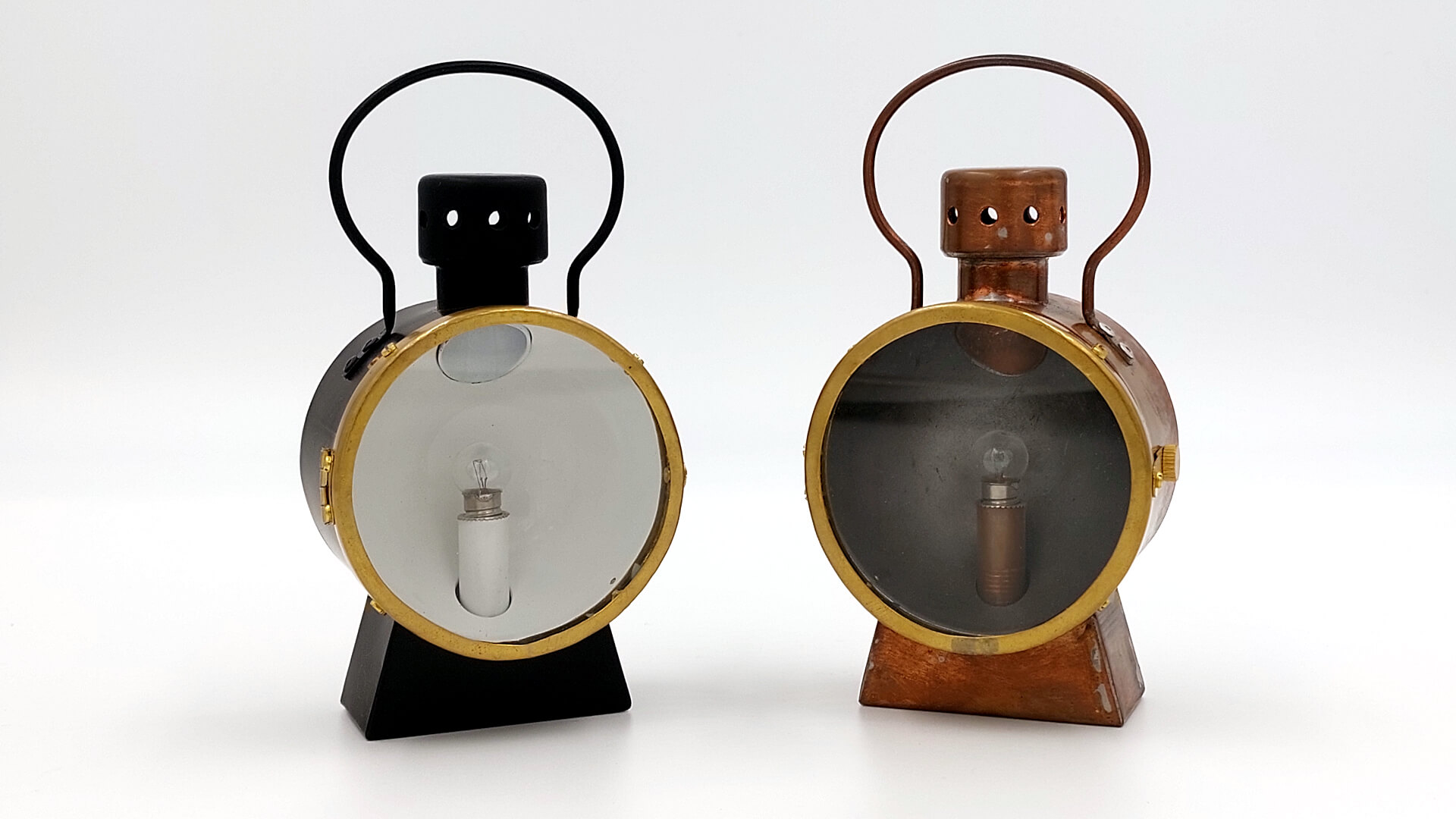
The lamps themselves are originals. Much like the Feldbahn 0-6-0 itself, they’re not scaled down from a specific model – but inspired by different designs. They are derived from German Feldbahn lamps and Swiss standard gauge lamps (see Feldbahn Lamp and SSB Lamp ).
If you’re looking for British lamps, you might not have to go through the hassle of building your owns – SRS has some nice Dual Aspect Locomotive Lamps for sale.
Materials and Hardware
Housing
- 80 mm copper rain pipe
- 22 x 1 mm copper tube (hard)
- 28 mm copper end cap
- 29 x 22 x 1.5 mm copper sealing ring
- 0.5 mm copper sheet
- 0.5 mm brass sheet
- M8 brass threaded rod
Reflector
- 1 mm steel hemisphere
Spectacles
- 0.5 mm brass sheet
- 2 mm glass disc
- brass hinge
- 0.3 mm spring steel
Handle
- 3 mm welding rod
Lamp Socket
- 12 x 1 mm copper tube (hard)
- M8 drive-in nut
- E10 lamp socket
Other Hardware
- 4x M2x2 mm brass cheese head screws
- 13x M2x4 mm brass cheese head screws
- 10x M2 brass nuts
- 1x M2 brass self-locking nut
- 1x M3 brass nut
- 1x M3 brass thumbscrew
- 1x E10 lamp (12V DC)
Fabrication
First of all, it is worth mentioning that all copper-based joints are soldered, not brazed. This decision is based on the idea to keep the temperatures and material costs low. Also, there will not be as many structural forces on the lamp that would require brazed joints. One exception to this has been made for the spectacles. They are made of a stripe of brass, and their one joint (to get an ‘O’) must withstand greater forces than a soldered joint can handle, when hammered to shape.
To prevent already-soldered edges from loosening when applying heat for a new joint, I submerged the piece(s) with their finished joints in a flat bowl of water. If the shape or size of the piece(s) didn’t allow for submersion, I wrapped a wet piece of rag around the area or positioned it near the water level, always making sure that the finished joints wouldn’t get hotter than boiling water.
I also opted to use the layout transfer method where possible, like in the other projects before. Essentially, I printed out my drawings in a 1:1 ratio and affixed them directly to the base material, allowing me to work on the project faster and with less margin for transfer errors. This is, of course, less accurate. Nevertheless, it is always sufficient to work only as accurately as the task requires.
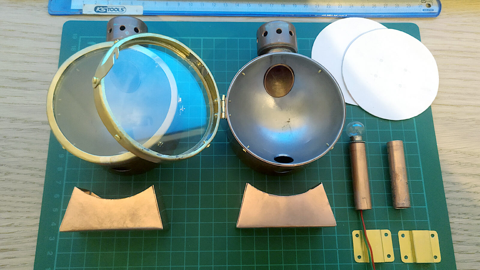
Housing
The three parts of the housing (reflector housing, chimney, and base) are first completed as independent units. They are joined together later in the building process.
Lid
The lid consist of two parts, an 8 mm wide ring that is soldered to the back side of the reflector housing (and thus becomes a part of it) and the actual lid itself. Both are cut out of 0.5 mm copper sheet and have four evenly spaced 2 mm holes to screw the lid to the reflector housing.
Reflector Housing
The reflector housing is made of 80 mm copper rain pipe, 45 mm long. The rain pipe was cut to length after I glued a 1:1 printed drawing to the surface. This drawing also marks the drill holes for the chimney, the lamp socket, the thumb screw, and the four equally spaced drill points for the later fixing of the reflector.
Before I drilled the holes, I pressed the reflector hemisphere into one end of the piece of rain pipe until their edges were flush with each other. Since the hemisphere has the same outer diameter as the rain pipe, this step creates a small outward bulge in the rain pipe.
In preparation to drill (or mill) the holes, I clamped the reflector in its housing between two pieces of wood in the vice. One of the wood pieces covered the entire open backside, and with the clamping force, the housing’s edge was gently pressed into it. This prevented deflection of the housing or even the whole assembly from breaking loose during the drilling process. The four holes (M2), to fix the reflector, also getting threaded immediately after drilling. This way, the tap has the same alignment as the drill.
At this point (the lid is already prepared for this), the components of the housing are getting soldered together. I also soldered five brass nuts to the inside of the reflector housing. One M3 nut to take the thumb screw for the locking mechanism and four M2 nuts to fasten the lid. Brass nuts are relatively cheap and provide a nice, sufficient thread for their counterparts. I positioned them with stainless screws through their designated holes. This has the advantage of not taking any of the solder and are therefore perfect fixings for the nuts to be soldered to the housing. Any excess material can be removed with a file after soldering.
Chimney and Cap
Chimney and cap are one part and made of 22 x 1 mm copper tube (hard, about 32 mm long), a 28 mm copper end cap, and a 29 x 22 x 1.5 mm copper sealing ring.
To drill the exhaust holes in the chimney cap, I again used the transfer method and wrapped a paper with marks for ten evenly spaced 4 mm holes around the cap.
Then all the parts got stacked onto each other and soldered together.
After all the holes on the reflector housing were drilled, the chimney could be fitted down its dedicated hole. This way, the still longer tube sticks into the reflector and the excess can be marked with a marker. This marking is then used to cut away the excess – I literally cut that away with a good pair of tin snips. A touch with the file did the finishing job and provides for a flush fit with the reflector.
Reservoir / Lamp Base
The lamp base is made of 0.5 mm copper sheet. After affixing the 1:1 drawing onto the copper sheet, I cut the sheet accordingly and beveled up the four sides. Then, the so created four edges were soldered together.
I also cut a piece of 8 mm M8 threaded brass rod, which will later serve as an attachment point for the lamp post. This will also be soldered in place before the base is soldered to the reflector housing.
Mounting
For the mounting, I used 0.5 mm brass sheet, cut a rectangle (35 x 22 mm) with round edges, and bent a bracket whose dimensions allow the Feldbahn’s lamp iron to fit through (when riveted to the lid). To make the blind rivets fit through the parts, I drilled four matching holes in the bracket and the lid. After the bracket was riveted on the lid, I took my rivet iron and hammered the blind side of the aluminium rivets round, for a nicer finish.
Spectacles
This is by far the most elaborate part of the project.
Starting off with a 15 mm wide stripe of 0.5 mm thick brass sheet, which gets silver soldered to a ring. Then the edges get hammered over, progressively, to form a 90° rim on both sides. One rim with a thickness of something between 3 and 4 mm, the rim on the other edge about 1 to 2 mm wide. I printed out a 1:1 drawing with all holes that had to be drilled to fixate the brackets to hold the glass disc as well as the bracket to lock the lamp later on, and the hinge.
After the whole assembly is put together, it is held against the lamp base with the reflector to mark the two drilling points, on the side, where the hinge is to be fixed. These two holes are threaded to take M2 screws.
When the photo (figure 1) was taken, I had no shorter M2 screws than 4 mm to hand. For the finished lamps, I replaced them with 2 mm screws, which are quite flat with the painted reflector.
Handle
Contrary to what the pictures suggest, the handle is made of 3 mm thick, copper-coated welding rod. I used a 1:1 drawing with some nails on the edges as a jig and a pair of round nose pliers to shape the welding rod. After I was pleased with the general shape, I hammered the ends flat, so they could be drilled to take four blind rivets ( 2 mm).
The position of the handle on the reflector housing is eyeballed and the holes are transferred to achieve a perfect match.
Lamp Socket
The lamp socket is basically a 50 mm long piece of 12 x 1 mm copper tube with a M8 drive-in nut inserted at the bottom end.
A piece of 8 mm long M8 brass rod is silver soldered onto the base of the housing, where the lamp socket is then screwed onto. The E10 lamp socket is a friction press fit into the copper tube. A hole for cabling is drilled into the tube – power source has yet to be determined (battery or external power).